Waterwingz (talk | contribs) (Added note about hardware LED dumper method being obsolete.) |
|||
| (41 intermediate revisions by 17 users not shown) | |||
| Line 1: | Line 1: | ||
| + | {| align="right" |
||
| − | __TOC__ |
+ | | __TOC__ |
| + | |} |
||
| + | =Introduction= |
||
| − | ===Q. What are the necessary steps to port the CHDK firmware on a DIGIC II/III cam which is currently not supported?=== |
||
| + | In order to port CHDK, you need a copy (dump) of the original firmware from the model you are trying to port. This page explains various methods of obtaining a dump. |
||
| + | For most cameras the [[Canon Basic/Scripts/Dumper|Canon Basic Dumper]] script is easiest and should be all you really need. The other methods mostly of historical interest. |
||
| − | '''A.''' Here is a basic description to give you an idea of the procedure. For more detailed explanations see the links below, especially [http://tools.assembla.com/chdk/wiki/HDK/Adding%20support%20for%20new%20camera this one]. |
||
| − | |||
| − | * First you need either the '''original firmware''' or a '''firmware dump''' of your camera.<br> |
||
| − | : The firmware dump can be obtained with a special ''firmware dumper'' which has to be adjusted for your camera. |
||
| − | :It is a firmware update file where one of the files inside (''WriterInFIR.bin'') has been patched in a way that it will make a memory dump onto the SD card. Usually this is possible if another platform-dependant code is disabled (this includes but is not limited to: LCD, LEDs, sound). |
||
| + | Once you have a dump, see [[Adding support for a new camera]]. |
||
| − | * Create a platform subdirectory for a new camera model/fw version (you can just copy an existing one). |
||
| + | =Canon Basic script= |
||
| − | * Find the adresses of the RAW-, video- and frame-buffers. |
||
| + | See [[Canon Basic/Scripts/Dumper]]. '''This is the recommended method''', which has been used for most cameras since it was discovered in 2010. |
||
| + | =Udumper= |
||
| − | * Modify a couple of addresses and constants. |
||
| + | '''NOTE''' This method will not work on recent (since 2009 or so) camera without modifications. |
||
| + | [[CardTricks]]<br /> is a graphical utility which includes udumper and a gui to prepare the card. |
||
| − | * Check the keyboard "driver" (button constants and behaviour). |
||
| + | You could also use UDumper without cardtricks. See [[Udumper]] and some related forum threads |
||
| − | * Check the addresses of autofound functions. Manually correct/find the right addresses for some of them with a disassembler like ''IDA Pro''. |
||
| ⚫ | |||
| + | * [http://chdk.setepontos.com/index.php/topic,745.msg6203.html TX1 Firmware dumping (Forum)] |
||
| + | =WIF Loader= |
||
| ⚫ | The method is to make/adapt the WIF loader. The base for developing it is an ''original firmware updater'' to similar camera models. As this loader has the functions to work with files, this way allow to save a dump of original firmware to SD-card. The main problem of using this method is that you have to pass all initialization stages of original firmware in order to be able to write to flash card. Used with: A620, A630, A640, A710, S2IS, S3IS |
||
| ⚫ | |||
| − | ===Q. How can I get a firmware dump?=== |
||
| + | '''NOTE : ''' The method described here is a lot of work and no longer necessary - use the Canon Basic Dumper. It has been left here for historical interest and out of respect for the effort of those who created it in the first place. |
||
| − | '''A.''' There are two ways known now: |
||
| − | |||
| − | ====Software method==== |
||
| − | ;Firmwares were gotten by this method |
||
| − | : A620, A630, A640, A710, S2IS, S3IS, IXUS70/SD1000 IXUS700, IXUS900IS, |
||
| − | |||
| ⚫ | The method is to make/adapt the WIF loader |
||
| − | |||
| − | There's a new dumper that has proven to work with a lot of new models witch can be found [http://ewavr.nm.ru/chdk/udumper.zip here]. It just copies the firmware of the camera on the sdcard. A little tutorial on how to use it is already written by someone. Please have a look at the [http://chdk.setepontos.com/index.php/topic,922.msg7711.html#msg7711 forum]. |
||
| − | |||
| − | :: Are the firmware dumpers for these models available? So one could start right ahead hacking away with these firmwares, and to have an example for new models. Thanks very much, [[User:PTT|PTT]] 02:08, 9 July 2007 (UTC) |
||
| − | :::There is the binary for A610e - http://vitalyb.mail333.com/a610/dump/ (I don't have sources). Also there is source code of S2/S3 dumper - http://grandag.nm.ru/hdk/dumper/ . But I did not look into it. --[[User:GrAnd|GrAnd]] 14:31, 9 July 2007 (UTC) |
||
| − | |||
| − | //remove that one if you think it's not necessary --[[User:Jetzt|jetzt]] 17:16, 11 March 2008 (UTC) |
||
| − | |||
| ⚫ | |||
| − | |||
| ⚫ | |||
[[Image:Blinker.jpg|right|thumb|150px|Receiver]] |
[[Image:Blinker.jpg|right|thumb|150px|Receiver]] |
||
;Firmwares were gotten by this method |
;Firmwares were gotten by this method |
||
| − | : A610, A700, A540, G7, SD630, A570IS, SD300, SD450, SD500, A560, SD1000, S5IS, A720 |
+ | : A610, A700, A540, G7, SD630, A570IS, SD300, SD450, SD500, A560, SD870, SD1000, SD1200IS, S5IS, A720, G11 |
This method is based on the 'blinking' of the original firmware through a led of the camera. You have to make a receiver (photodiode or phototransistor), the software to write a dump, decoder and a tiny firmware which outputs its firmware through the led. The receiver can be connected to serial port (you need to emulate the UART in the camera in this case) or to microphone input. |
This method is based on the 'blinking' of the original firmware through a led of the camera. You have to make a receiver (photodiode or phototransistor), the software to write a dump, decoder and a tiny firmware which outputs its firmware through the led. The receiver can be connected to serial port (you need to emulate the UART in the camera in this case) or to microphone input. |
||
| − | :<i>'''Note''': Many people have had trouble trying to obtain a photo-diode or photo-transistor for this task. Do you have an old ball-driven mouse in a junk-box? Each X and Y axis is read by the rotation of a notched wheel passing through the light-path |
+ | :<i>'''Note''': Many people have had trouble trying to obtain a photo-diode or photo-transistor for this task. Do you have an old ball-driven mouse in a junk-box? Each X and Y axis is read by the rotation of a notched wheel passing through the light-path between IR LED (transmitter) and a photo-diode detector. The optical device you need is easily salvaged from that. Caution: Many of the mouse photodiodes are ONLY sensetive for infrared light. These photodiodes can not be used for firmware dumping, because they can not "see" the LED light from the camera.</i> |
| − | + | ==Using soundcard input== |
|
| − | I used the microphone input. All necessary files (with sources) you can get [http:// |
+ | I used the microphone input. All necessary files (with sources) you can get '''[http://drop.io/chdkdevelopment/asset/by-grand-blinker-rar-rar here]'''. |
'''The scheme''' I used: |
'''The scheme''' I used: |
||
| Line 62: | Line 50: | ||
| |----------------+ |
| |----------------+ |
||
| | phototransistor |
| | phototransistor |
||
| − | +=======+ BPW96C or |
+ | +=======+ BPW96C or equivalent |
| | |
| | |
||
| Line 70: | Line 58: | ||
</pre> |
</pre> |
||
| − | '''The transmitting protocol'''<br> |
+ | '''The transmitting protocol'''<br /> |
* '''Header''' (3600 bytes) - "0123456789" sequence for visual control of data. |
* '''Header''' (3600 bytes) - "0123456789" sequence for visual control of data. |
||
* '''Blocks''' - 4096 blocks of 1K data |
* '''Blocks''' - 4096 blocks of 1K data |
||
| Line 77: | Line 65: | ||
:* '''CRC16 x 2''' (4 bytes) - CRC16 of block (repeated twice) |
:* '''CRC16 x 2''' (4 bytes) - CRC16 of block (repeated twice) |
||
| − | Each byte is encoded in the following way:<br> |
+ | Each byte is encoded in the following way:<br /> |
| − | [[Image:Shim.png|Signal levels]]<br>,where: |
+ | [[Image:Shim.png|Signal levels]]<br />,where: |
# Spacing between bytes |
# Spacing between bytes |
||
# Spacing between bits |
# Spacing between bits |
||
| Line 87: | Line 75: | ||
* Connect the receiver to the microphone input of sound card. |
* Connect the receiver to the microphone input of sound card. |
||
* Run a recording application (I used Adobe Audition) with the following parameters: 96KHz (it's adjustable), 8 bit, mono. |
* Run a recording application (I used Adobe Audition) with the following parameters: 96KHz (it's adjustable), 8 bit, mono. |
||
| − | * Direct 'blinking' led |
+ | * Direct 'blinking' led at the receiver (BPW96C). |
| − | * Start the recording. Start the 'blinking' firmware. |
+ | * Start the recording. Start transmition of the 'blinking' firmware. |
| − | * Wait for process |
+ | * Wait for process to be finished (1-7 hours depends on speed chosen). The camera will be switched off at the end. |
* Save the data to the PCM-file (8-bit unsigned raw data, not WAV!). |
* Save the data to the PCM-file (8-bit unsigned raw data, not WAV!). |
||
| − | * Process the file by 'adc.exe |
+ | * Process the file by 'adc.exe <filename>'. You will get 'dump'-file. |
* Run 'dec.exe'. You will get 'dump.dat'-file. This file is the firmware. |
* Run 'dec.exe'. You will get 'dump.dat'-file. This file is the firmware. |
||
| − | '''Speed/signal adjusting:'''<br> |
+ | '''Speed/signal adjusting:'''<br /> |
| − | + | It may be required to do some adjustments depended on camera/led/receiver used. The main idea is to get 'readable' signal as shown on the picture above.<br /> |
|
Here the values for certain speeds and leds for A610. |
Here the values for certain speeds and leds for A610. |
||
<pre> |
<pre> |
||
| Line 149: | Line 137: | ||
</pre> |
</pre> |
||
| ⚫ | |||
| ⚫ | |||
| ⚫ | |||
| + | [[Image:UART_receiver.jpeg|200px|UART receiver by GrAnd]] [[File:G7 blinking RS232 ewavr.jpg|200px|This is the blinker setup used by ewavr to blink the G7 via RS232]] |
||
| ⚫ | |||
| − | [[Image:UART_receiver.jpeg|200px]] |
||
The photodiode used is a generic one. You may need to test the distance to the camera's AF LED which fits you better, mine worked properly at about 20cm (8 inches) away, YMMV. |
The photodiode used is a generic one. You may need to test the distance to the camera's AF LED which fits you better, mine worked properly at about 20cm (8 inches) away, YMMV. |
||
| − | (side info: you can hardly see the LED |
+ | (side info: you can hardly see the LED blinking because it is very fast but it is still perfectly readable by the photodiode, so do not worry.) The resistance in the circuit shown above has got 10 kOhm. Depending on the photodiode the resistance should also have 200 Ohm for best use. |
| − | You also need the camera blinker and serial port loader programs |
+ | You also need the camera blinker and serial port loader programs. You can find the original version written in Pascal [http://grandag.nm.ru/hdk/blinker/blink_g7.rar here]. An other converted version to Java with CRC16 is available [http://chdk.setepontos.com/index.php?action=dlattach;topic=3547.0;attach=3563 here]. |
| ⚫ | |||
| ⚫ | |||
| ⚫ | |||
| + | The first version contains these two parts: |
||
| ⚫ | |||
| ⚫ | |||
| ⚫ | |||
| ⚫ | |||
| + | |||
| + | The second version contains these two parts: |
||
| + | #Camera: Source code main.c which have to build for your camera. See details in Readme.txt |
||
| + | #PC: Compiled Java program Load.class. See details in Readme.txt |
||
| + | |||
| ⚫ | |||
* ''Display'' tab: Hex + Ascii, set "Scrollback" for 2000 lines or so, increase the rows count too. |
* ''Display'' tab: Hex + Ascii, set "Scrollback" for 2000 lines or so, increase the rows count too. |
||
| − | * ''Port'' tab: 9600 8N1, set your serial port number and '''don't forget''' to click on "Change". |
+ | * ''Port'' tab: 9600 8N1,(transmission speed 9600 bits per second, 8 bits, No-parity, 1-stop pulse at the end of byte) set your serial port number and '''don't forget''' to click on "Change". |
* ''Capture'' tab: the filename you want to dump to, untick "Direct Capture" if you want to watch it going. |
* ''Capture'' tab: the filename you want to dump to, untick "Direct Capture" if you want to watch it going. |
||
| − | * ''Pins'' tab: '''Make sure''' to "Clear" DTR(4). |
+ | * ''Pins'' tab: '''Make sure''' to "Clear" DTR(4) (Clear Data Terminal Ready-signal used if "hardware hand shacking" is used during transmission). |
| − | While capturing you can see the file grow and the speed rate in the status line at the bottom. It should be a figure around |
+ | While capturing you can see the file grow and the speed rate in the status line at the bottom. It should be a figure around 800 CPS (characters per second). |
'''The real action:''' |
'''The real action:''' |
||
| Line 177: | Line 171: | ||
#Properly align AF led and the receiver photodiode. |
#Properly align AF led and the receiver photodiode. |
||
#Start ''load.exe''. in a DOS terminal. You have 10 seconds to start blinker or it will timeout. Alternatively Press on "start overwriting" to start capture in ''realterm'', there is no timeout here. |
#Start ''load.exe''. in a DOS terminal. You have 10 seconds to start blinker or it will timeout. Alternatively Press on "start overwriting" to start capture in ''realterm'', there is no timeout here. |
||
| − | #start the blinker "firmware" in the camera following the usual firmware update procedure. You should see the AF light turn on and load.exe writing |
+ | #start the blinker "firmware" in the camera following the usual firmware update procedure. You should see the AF light turn on and load.exe writing data to terminal... |
| − | c: |
+ | c:> ''load com1 firmware1.fir''Received1kbyte.Received2kbyte. ...Received2048kbyte. |
| − | Received1kbyte. |
||
| − | Received2kbyte. |
||
| − | ... |
||
| − | Received2048kbyte. |
||
| − | ''load.exe'' will timeout after 10 seconds at blink's end |
+ | ''load.exe'' will timeout after 10 seconds at blink's end. For ''realterm'' you'll need to manually stop capturing when the AF led comes off. Once done, reload your camera's battery. |
For G7 you may need to repeat the above procedure using PS2.fir to get the firmware's second part. |
For G7 you may need to repeat the above procedure using PS2.fir to get the firmware's second part. |
||
Open the downloaded firmware files in a HEX Editor and cut off the ''lead in'' information (.....xx xx xx begin) and the ''load out'' (end.). |
Open the downloaded firmware files in a HEX Editor and cut off the ''lead in'' information (.....xx xx xx begin) and the ''load out'' (end.). |
||
| − | Now you have two files with all the necessary data in it. To join |
+ | Now you have two files with all the necessary data in it. To join two files just do ''copy firmware1.fir + firmware2.fir Firmware.bin'' and you have single firmware file in your hands. |
| + | *'''An detailed description of the SX200 blinking process with the used hardware and software is here: [[Blinking the firmware to the RS232 interface]]''' |
||
'''The wired solution''' |
'''The wired solution''' |
||
| − | |||
You can also go hardcore and open the camera and look for the LED connections (you will not need the phototransistor) to get a more reliable connection. If you are brave enough you can find the instructions [http://hackinghood.googlepages.com/home here] |
You can also go hardcore and open the camera and look for the LED connections (you will not need the phototransistor) to get a more reliable connection. If you are brave enough you can find the instructions [http://hackinghood.googlepages.com/home here] |
||
| + | =Firmware= |
||
| ⚫ | |||
| + | ==ROM start addresses== |
||
| − | ---- |
||
| + | Known ROM start addresses are: |
||
| − | |||
| + | <table> |
||
| − | [http://tools.assembla.com/chdk/wiki/HDK/Adding%20support%20for%20new%20camera Instruction]<br> |
||
| + | <tr><td>0xFF000000</td><td>Used by some cameras starting in 2011</td></tr> |
||
| − | [http://vitalyb.mail333.com/hdk/FAQ.ENG.txt Vitaly's FAQ]<br> |
||
| + | <tr><td>0xFF810000</td><td>Most 2010 and earlier S-, SD-, G- and some A- series</td></tr> |
||
| ⚫ | |||
| + | <tr><td>0xFFC00000</td><td>Mostly older A- series.</td></tr> |
||
| − | [http://tools.assembla.com/chdk/wiki/HDK/%D0%9F%D0%BE%D0%BB%D0%B5%D0%B7%D0%BD%D0%B0%D1%8F%20%D0%B8%D0%BD%D1%84%D0%BE%D1%80%D0%BC%D0%B0%D1%86%D0%B8%D1%8F%20%D0%BE%20%D1%80%D0%B0%D0%B1%D0%BE%D1%82%D0%B5%20%D0%BF%D1%80%D0%BE%D1%88%D0%B8%D0%B2%D0%BA%D0%B8 List of Property Cases]<br> |
||
| + | </table> |
||
| − | [[PropertyCase|List of Property Cases]] |
||
| − | |||
| ⚫ | |||
| ⚫ | |||
| + | * [[Adding support of a new camera]] |
||
| + | * [[Modifying the CHDK Sources]] |
||
| + | * [[DryOS Porting]] |
||
| + | * [[Adding Firmware Features]] |
||
| ⚫ | |||
| + | * [[Compiling CHDK under Windows]] |
||
| + | * [[For Developers]] |
||
| + | * [[Loading dump to IDA]] |
||
| + | * [http://chdk.setepontos.com/index.php/topic,1454.0.html How does CHDK start running ? ''(Forum)''] |
||
| ⚫ | |||
| + | [[Category:Firmware]] |
||
| + | [[Category:Porting]] |
||
Revision as of 23:40, 11 March 2012
Introduction
In order to port CHDK, you need a copy (dump) of the original firmware from the model you are trying to port. This page explains various methods of obtaining a dump.
For most cameras the Canon Basic Dumper script is easiest and should be all you really need. The other methods mostly of historical interest.
Once you have a dump, see Adding support for a new camera.
Canon Basic script
See Canon Basic/Scripts/Dumper. This is the recommended method, which has been used for most cameras since it was discovered in 2010.
Udumper
NOTE This method will not work on recent (since 2009 or so) camera without modifications.
CardTricks
is a graphical utility which includes udumper and a gui to prepare the card.
You could also use UDumper without cardtricks. See Udumper and some related forum threads
WIF Loader
The method is to make/adapt the WIF loader. The base for developing it is an original firmware updater to similar camera models. As this loader has the functions to work with files, this way allow to save a dump of original firmware to SD-card. The main problem of using this method is that you have to pass all initialization stages of original firmware in order to be able to write to flash card. Used with: A620, A630, A640, A710, S2IS, S3IS
Hardware-software solution
NOTE : The method described here is a lot of work and no longer necessary - use the Canon Basic Dumper. It has been left here for historical interest and out of respect for the effort of those who created it in the first place.
Receiver
- Firmwares were gotten by this method
- A610, A700, A540, G7, SD630, A570IS, SD300, SD450, SD500, A560, SD870, SD1000, SD1200IS, S5IS, A720, G11
This method is based on the 'blinking' of the original firmware through a led of the camera. You have to make a receiver (photodiode or phototransistor), the software to write a dump, decoder and a tiny firmware which outputs its firmware through the led. The receiver can be connected to serial port (you need to emulate the UART in the camera in this case) or to microphone input.
- Note: Many people have had trouble trying to obtain a photo-diode or photo-transistor for this task. Do you have an old ball-driven mouse in a junk-box? Each X and Y axis is read by the rotation of a notched wheel passing through the light-path between IR LED (transmitter) and a photo-diode detector. The optical device you need is easily salvaged from that. Caution: Many of the mouse photodiodes are ONLY sensetive for infrared light. These photodiodes can not be used for firmware dumping, because they can not "see" the LED light from the camera.
Using soundcard input
I used the microphone input. All necessary files (with sources) you can get here.
The scheme I used:
    / \
   |   |
    \ /        +-----------+
   +===+       |           |            |----\
   |   |-------+       ----*------------|     |
   |===|            ----*---------------|     |
   |   |                |               |----/
   |   |----------------+
   |   |                       phototransistor
 +=======+                     BPW96C or equivalent
 |       |

 3.5mm plug
 to mic-in
 of soundcard
The transmitting protocol
- Header (3600 bytes) - "0123456789" sequence for visual control of data.
- Blocks - 4096 blocks of 1K data
- Address (4 bytes) - address of the current block
- Data (1024 bytes) - piece of firmware
- CRC16 x 2 (4 bytes) - CRC16 of block (repeated twice)
Each byte is encoded in the following way:
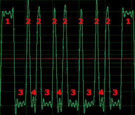
,where:
- Spacing between bytes
- Spacing between bits
- Wide pulse - logical "1"
- Narrow pulse - logical "0"
The usage flow:
- Connect the receiver to the microphone input of sound card.
- Run a recording application (I used Adobe Audition) with the following parameters: 96KHz (it's adjustable), 8 bit, mono.
- Direct 'blinking' led at the receiver (BPW96C).
- Start the recording. Start transmition of the 'blinking' firmware.
- Wait for process to be finished (1-7 hours depends on speed chosen). The camera will be switched off at the end.
- Save the data to the PCM-file (8-bit unsigned raw data, not WAV!).
- Process the file by 'adc.exe <filename>'. You will get 'dump'-file.
- Run 'dec.exe'. You will get 'dump.dat'-file. This file is the firmware.
Speed/signal adjusting:
It may be required to do some adjustments depended on camera/led/receiver used. The main idea is to get 'readable' signal as shown on the picture above.
Here the values for certain speeds and leds for A610.
A610 - AF beam, FAST (9230 bod) [96KHz]
--------------------------
fw:
  #define DELAY_SYNC   45
  #define DELAY_SPACE  50
  #define DELAY0       1
  #define DELAY1       25

decode:
  #define LEVEL_THRES_HI  0xA0
  #define LEVEL_THRES_LO  0x80
  #define LEN_SYNC        5
  #define LEN_SPACE       1
  #define LEN_0           1
  #define LEN_1           6


A610 - AF beam, SLOW (2500 bod ) [96KHz]
-------------------------
fw:
  #define DELAY_SYNC   400
  #define DELAY_SPACE  100
  #define DELAY0       100
  #define DELAY1       200

decode:
  #define LEVEL_THRES_HI  0xA0
  #define LEVEL_THRES_LO  0x80
  #define LEN_SYNC        40
  #define LEN_SPACE       5
  #define LEN_0           12
  #define LEN_1           24

A610 - BLUE_led (1600 bod) [11KHz]
-------------------------
fw:
  #define DELAY_SYNC   400
  #define DELAY_SPACE  175
  #define DELAY0       150
  #define DELAY1       350

decode:
  #define LEVEL_THRES_HI  0x90
  #define LEVEL_THRES_LO  0x70
  #define LEN_SYNC        7
  #define LEN_SPACE       1
  #define LEN_0           1
  #define LEN_1           4
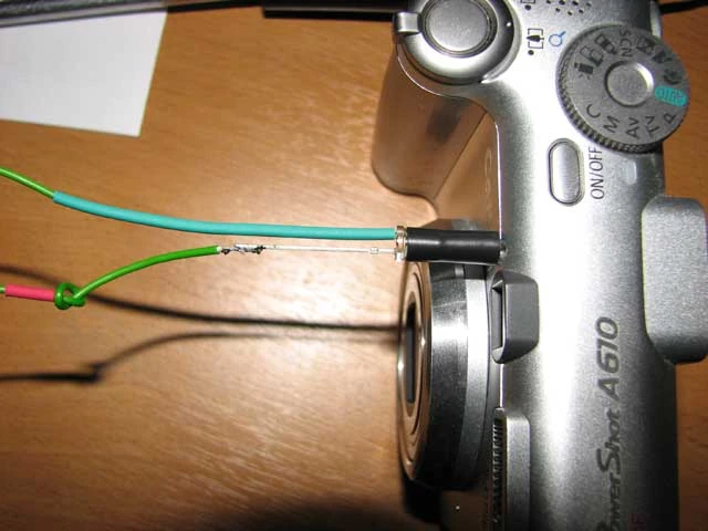
Serial port download solution
You can download (blink) the firmware using your computer's serial port instead of sound card as input device. You may need a photodiode connected to serial port according to the following schematic:
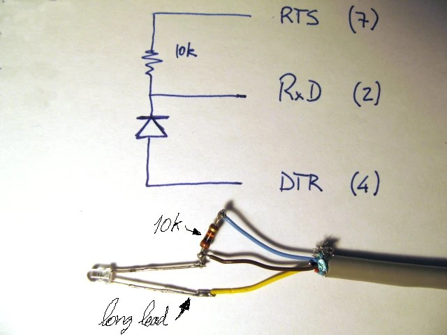
The photodiode used is a generic one. You may need to test the distance to the camera's AF LED which fits you better, mine worked properly at about 20cm (8 inches) away, YMMV.
(side info: you can hardly see the LED blinking because it is very fast but it is still perfectly readable by the photodiode, so do not worry.) The resistance in the circuit shown above has got 10 kOhm. Depending on the photodiode the resistance should also have 200 Ohm for best use.
You also need the camera blinker and serial port loader programs. You can find the original version written in Pascal here. An other converted version to Java with CRC16 is available here.
The first version contains these two parts:
- Camera: PS1.fir and PS2.fir which are the camera's blinkers for Canon Powershot G7. This has been split in two for easer repetition of downloading in case of failure, (it takes around 40 minutes each to download for G7). I guess you can use your camera's own blinker here instead.
- PS: load.exe which is the serial receiver program for Windows. The syntax is
load <serial port #> <dump filename>
The second version contains these two parts:
- Camera: Source code main.c which have to build for your camera. See details in Readme.txt
- PC: Compiled Java program Load.class. See details in Readme.txt
Alternatively to load.exe/Load.class you can use realterm for both monitoring the serial port and capturing the file at the same time. Make sure you configure it like this...
- Display tab: Hex + Ascii, set "Scrollback" for 2000 lines or so, increase the rows count too.
- Port tab: 9600 8N1,(transmission speed 9600 bits per second, 8 bits, No-parity, 1-stop pulse at the end of byte) set your serial port number and don't forget to click on "Change".
- Capture tab: the filename you want to dump to, untick "Direct Capture" if you want to watch it going.
- Pins tab: Make sure to "Clear" DTR(4) (Clear Data Terminal Ready-signal used if "hardware hand shacking" is used during transmission).
While capturing you can see the file grow and the speed rate in the status line at the bottom. It should be a figure around 800 CPS (characters per second).
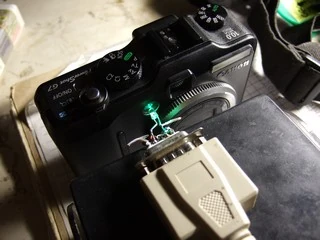
The real action:
- Connect the photoreceiver to the computer's serial port.
- Properly align AF led and the receiver photodiode.
- Start load.exe. in a DOS terminal. You have 10 seconds to start blinker or it will timeout. Alternatively Press on "start overwriting" to start capture in realterm, there is no timeout here.
- start the blinker "firmware" in the camera following the usual firmware update procedure. You should see the AF light turn on and load.exe writing data to terminal...
c:> load com1 firmware1.firReceived1kbyte.Received2kbyte. ...Received2048kbyte.
load.exe will timeout after 10 seconds at blink's end. For realterm you'll need to manually stop capturing when the AF led comes off. Once done, reload your camera's battery. For G7 you may need to repeat the above procedure using PS2.fir to get the firmware's second part.
Open the downloaded firmware files in a HEX Editor and cut off the lead in information (.....xx xx xx begin) and the load out (end.). Now you have two files with all the necessary data in it. To join two files just do copy firmware1.fir + firmware2.fir Firmware.bin and you have single firmware file in your hands.
- An detailed description of the SX200 blinking process with the used hardware and software is here: Blinking the firmware to the RS232 interface
The wired solution You can also go hardcore and open the camera and look for the LED connections (you will not need the phototransistor) to get a more reliable connection. If you are brave enough you can find the instructions here
Firmware
ROM start addresses
Known ROM start addresses are:
| 0xFF000000 | Used by some cameras starting in 2011 |
| 0xFF810000 | Most 2010 and earlier S-, SD-, G- and some A- series |
| 0xFFC00000 | Mostly older A- series. |